This is a memo regarding NSX-T uplinks. I think this is the most confusing and difficult part to understand in NSX-T. This post is made of 3 sections, Diagram with a more visual approach, Component with remarks/comments on uplinks components and a Q&A section based on questions I was asking myself. You can find duplicate information but slightly rephrased in every section. I kept it that way as some time some form are easier to understand than other. If you spot errors don’t hesitate to contact me.
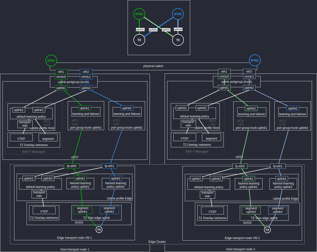
Diagram
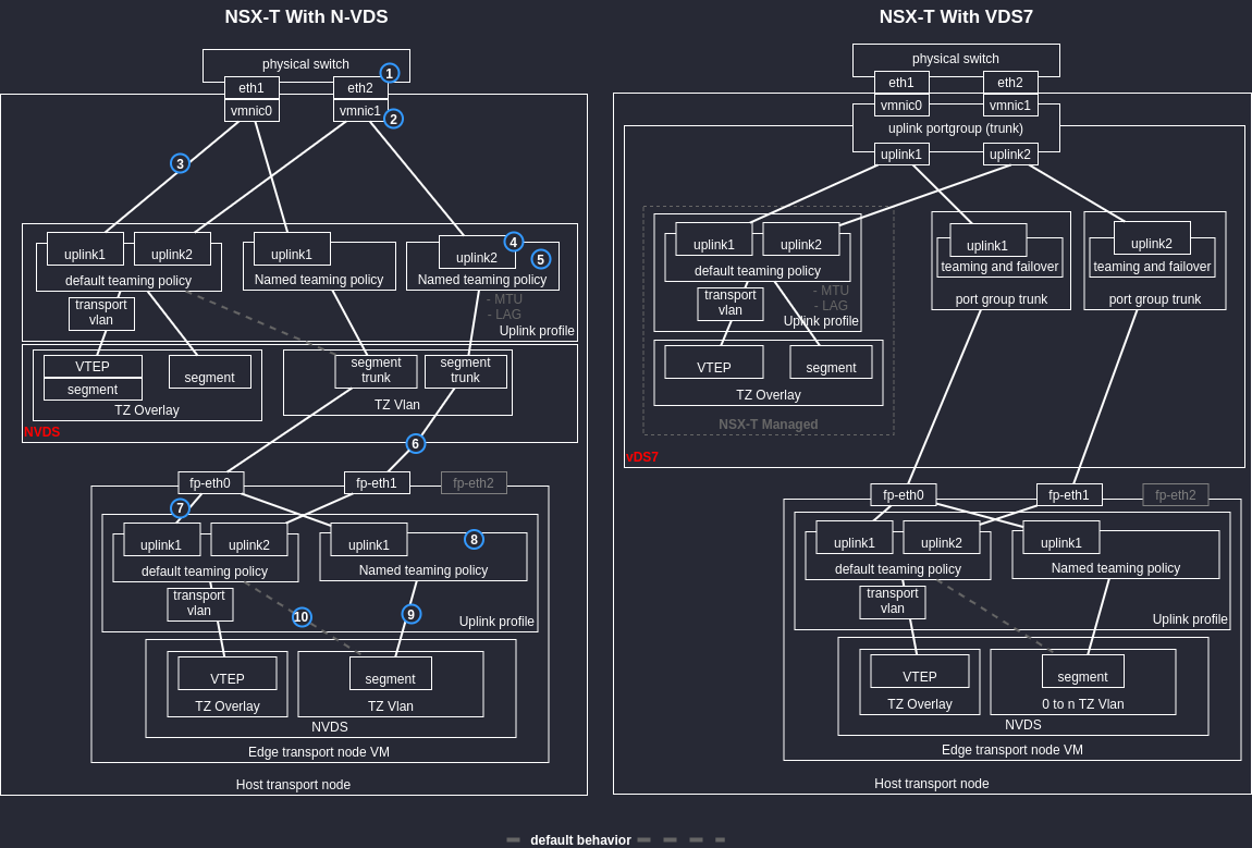
Legend
- Switch port trunk (vlan id of vteps + uplinks)
- Prior to vDS7, physical interfaces are exclusive to NVDS or vDS.
- The association is done when the host is configured for NSX-T then the uplink profile is associated to the transport node.
- If you want to use the same physical interfaces as the default profile, the uplink name on the named teaming policy has to be identical.
- If you put 2 active interfaces in your named teaming policy you lose the benefit of having deterministic uplink for you Edge/T0 uplinks. If you put active/standby interface here, you can’t have active/active interfaces in the default teaming policy.
- This Edge VM interface is attached through vcenter to the NSX-T Switch or vDS7 port group. This is like the interface of the host connected to the physical switch in the first point.
- Uplink to interface mapping is done when the uplink profile association to the transport node is done.
- If we add a second standby uplink in the Named Teaming Policy, it impact the default teaming policy. You will not be able to have the 2 uplinks active at the same time. It’s those better to have a single uplink in the Named Teaming Policy if you want to have active/active links in the default teaming policy. Named Teaming Policy are available only for segment of type vlan. See also point 5.
- In the Transport Zone, any Named Teaming Policy from any Uplink Profile can be selected. On the segment vlan, any Named Teaming Policy associated with the TZ can be chosen. The issue being that if the Segment Vlan is then used on a Transport Node with an Uplink Profile which don’t have the Named Teaming Policy defined it will not works. NSX-T doesn’t see any error. Also you never know if the Named Teaming Policy defined in an Uplink Profile are used.
- Default behavior if we don’t want any specific behavior for the uplinks.
Components
Location (NSX-T 3.1)
System -> Fabric -> Profiles -> Uplink Profile
   - Transport VLAN
   - MTU
   - LAG
   - Teamings
      - Default Teaming -> Uplink
      - Add -> Named (Named teaming policy) -> Uplink

System -> Fabric -> Transport Zone
  - Named teaming policy

System -> Nodes
  - hostswitch name/vds name
  - Transport Zone
  - Uplink profile
     - Uplink -> physical nic

Networking -> Segment
   - Transport Zone (vlan or overlay)
   - Uplink Teaming Policy (Named teaming policy only for TZ Vlan)
Remarks
Uplink profile
Used with Transport Node (Edge and Host)
- Teaming policy
- Named policy can be selected in “Uplink Teaming Policy” of segment VLAN configuration
- The default is the one selected for the overlay uplink/VTEP and is the same for all overlay segment.
- Named policy can be selected in “Uplink Teaming Policy” of segment VLAN configuration
Teaming policy
- On the vlan segment
Only Named Teaming Policy that are associated to the Transport Zone vlan can be selected - On the overlay segment
The teaming policy of the uplink can’t be changed. It’s inherited from the one applied to the transport node via the uplink profile - On the transport node
The uplink profile selected define the default teaming policy that will be applied and the possible Named Teaming Policy for the segment vlan (Edge)
Transport Zone
- Used with Transport Node (Edge and Host)
- Allows to tie the segments to the TN.
The Named Uplink Policy is the Named Teaming Policy that can be used by a segment vlan tied to the Transport Zone. If there is nothing that mean it will pick the default policy of the uplink profile associated with the TN - Uplink interfaces of the Edge VM are defined in the uplink of the TN according to the uplink profile (if in the profile you have dedicated interface for uplinks, you need to create Named Teaming Policy for them with different uplink names).
Edge Uplinks
The IP address of the uplink is assigned on the T0 within a logical/virtual interface. You can’t select the physical interface, you select the edge node and the segment where to assign the IP. Then you can have 1 or 2 physical uplinks based on the default teaming policy of the uplink profile of the edge node or the named teaming policy associated on the segment vlan. This policy can have active/active teaming and those the link selected for the outgoing traffic is based on the load balance algorithm of the teaming policy. See also Q&A point 4.
To have different behavior between the overlay uplinks and the exit uplinks you need to have the exit uplinks behaviors configured as Named Teaming Policy in the uplink profile that you will associate to the TN.
On the physical links you can end up having policies for the Host overlay (default teaming policy of the host uplink profile), Edge VM overlay (default teaming policy of the edge VM uplink profile), Edge VM uplink (named teaming policy of the edge VM uplink profile).
Q&A
Click to see the Q&A
- Does the vtep of a transport node inherit the uplink profile associated with the transport node ?
- Yes
- Yes
- Is the port group on the vCenter VDS7 only for vlan segment (non overlay) ?
- Yes, for Edge VM uplink
- Yes, for Edge VM uplink
- Does the teaming and failover policy of the port group of the host conflict with the uplink profile of the Edge VM ?
- No, there is no conflict, just different purposes. The one on the port group will define what interface you will use as uplink for the host. If you use two physical interfaces as uplinks in the Port Group while you have only one virtual interface of the Edge VM connected on it, you loose the purpose to have deterministic uplinks.
- No, there is no conflict, just different purposes. The one on the port group will define what interface you will use as uplink for the host. If you use two physical interfaces as uplinks in the Port Group while you have only one virtual interface of the Edge VM connected on it, you loose the purpose to have deterministic uplinks.
- Is this possible to have 2 interfaces active/active for an uplink transport vlan ?
- Yes, the interface selected will be based on the load balancing method.
- Yes, the interface selected will be based on the load balancing method.
- Can we have different policies between overlay interface and uplink interfaces ?
- Yes, you need to specify named teaming policy and associate it to the segment vlan of the uplink.
- Yes, you need to specify named teaming policy and associate it to the segment vlan of the uplink.
- What if no named teaming policy is selected on the segment vlan ?
- It uses the default teaming policy of the uplink profile of the node where the segment is deployed.
- It uses the default teaming policy of the uplink profile of the node where the segment is deployed.
- Is this possible to have a named teaming policy for overlay?
- No
- No
- Does the uplink profile on the transport node override the one of the Transport Node Profile ? Which one takes precedence ?
- If you change the Transport Node Profile parameters it will override the node configuration as much as there is no Transport Zone already used or interface already configured, otherwise an error will be triggered. You can override the Transport Node Profile by changing the parameters individually on a node but then you have a warning message because you have mismatches in the node cluster between transport node.
- If you change the Transport Node Profile parameters it will override the node configuration as much as there is no Transport Zone already used or interface already configured, otherwise an error will be triggered. You can override the Transport Node Profile by changing the parameters individually on a node but then you have a warning message because you have mismatches in the node cluster between transport node.
- Uplink overlay of the Edge VM are defined on the same physical link as the Host transport node, can it have different policy ?
- Yes, see the diagram. If you use named teaming policy (NVDS) or port group (vDS7) for the Edge VM interfaces.
- Yes, see the diagram. If you use named teaming policy (NVDS) or port group (vDS7) for the Edge VM interfaces.
- In the case where you have 2 active physical interfaces, how do you know the physical interface used by the vteps IP address ?
- I don’t think you can.
- I don’t think you can.
- What is the behavior of a host with a single vtep if the two uplinks are active/active ?
- I think it’s behaves like in the point 4.
- I think it’s behaves like in the point 4.
- What if we use the same vtep subnets for Edge VM and host ?
- This is only possible starting from 3.1
- This is only possible starting from 3.1
- How many virtual switch and Transport Zone can we have on a TN ?
Those numbers can change and are not official. Don’t quote me on these.
- TN can have up to 4 N-VDS (hostswitch)
- N-VDS can only have one TZ Overlay
- Host TN can have multiple TZ Overlay, 1 per N-VDS so 4 in total
- Edge TN can have only one TZ Overlay
- One N-VDS can have multiple TZ VLAN
- If we want 4 TZ Overlay it’s better to have the TZ vlan on the same NVDS as the TZ Overlay.
- TN can have up to 4 N-VDS (hostswitch)
Examples